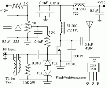
The 60 Watt linear rf amplifier is easy all solid state circuit applying power mosfet IRF840. The IRF series of power transistors are provided in a number of voltage and power ratings. A single IRF840 can carry out maximum power output of 125 watts. Because these transistors are applied in inverters and smps, they're simply presented for about Rs: 20/-.
The IRF linear amplifier could be connected to the out put of well-known VWN-QRP to obtain an output of 60 Watts. The circuit draws 700 ma at 60 Volt Vcc. Great heat sink is actually a ought to for the power transistor.
Alignment of the circuit is quite effortless. Connect a dummy load to the out put of the circuit. It is possible to use some modest bulb like 24V 6Watts as the dummy load. I've even utilized 230V 60Watts bulb as dummy load with my IRF840 power amplifier working at 120Volts. Adjust the 10K preset to obtain about 100 ma Drain current. I applied gate voltage of 0.8V with my linear amplifier. A heigh gate voltage can make the power transistor get distroyed by self oscillation. So gate voltage ought to be below 2V and fixing at 1V is going to be secure.
Bifalar transformaer T1 is wound with 8 turns 26SWG on 1.4 x 1 balun core. The coil on the drain of IRF is 3 turns 20 SWG wound on 4 number of T13.9 torroids (two torroids are stacked to form a balun core). The RFC at the Vcc line is 20 Turns 20 SWG wound on T20 torroid.
60W Linear RF Amplifier circuit source:
http://www.flashwebhost.com/circuit/60_watts_rf_amplifier.php

No comments:
Post a Comment