Saturday 13 August 2011

100Watt Bipolar Power Amplifier Circuit with BD139-BD140


This is a basic 100 watt power amplifier designed to be (relatively) easy to build at a reasonable price. It has a better performance (read: musical quality) than the standard STK module amps that are used in almost every mass market stereo receiver manufactured today. When I originally built this thing, it was because I needed a 100 WPC amp and do not want any money. So I designed around parts I had in the store.
The design is actually a standard format, and I’m sure there are commercial entities that are similar. To my knowlwdge, it is not an exact copy of a commercial entity, nor am I aware of any patents on topology. For experienced builders: I am aware that many improvements and adjustments can be made, but the idea was to keep it simple and must do-able by anyone who is a circuit, and has not the patience to do a sloppy job.
If friend want Bipolar Transistor power amplifier circuit. , In model HIFI OCL 100W RMS. I think this track should be an interesting choice, this circuit is the use of the key transistor BD317 and BD318 unless transistor number BD139, BD140, BC556 too easy then try to buy when the 35V power source with only then build is not difficult for other details as the result of a few See Circuit.  Input stage is a BC556 transistor, which most of the open loop gain, and on the serene DC voltage stabilizes. This feeds a level shift stage where the voltage swing to (-) track references. The Transconductance stage is a Darlington, improve frerqency high linearity. The BD317, 318 on a rather large collector-base capacity is dependent on voltage. The BD319 presents this low-z and has a C (ob) of only a few of PF, which is effectively swamped by the pole-splitting 220pF cap. The scene is supplied by BC546 active load (current), which is approximately 20 mA. The current, until the BC556 is limited to about 70 mA in the worst cases.
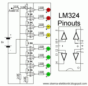
Audio Level Meter with 8 LEDs Indicator

This audio level meter required 2 pieces of LM324 for each channel. Every single LM324 contain 4 op-amps, then you need 2 pieces of LM324 to cover 8 LEDs. And need 4 piece of LM324 for 16 LEDs (for stereo channel)
Here the schematic:
Audio Level Meter with 8 LEDs Indicator circuit diagram

Amplifier Power Indicator

This is one of many audio level indicator circuit. The different is that this circuit should be connected tho the output of amplifier while the other indicators connected before amplifier module. This circuit will show the real audio output by LED indicator level.

Amplifier Power Indicator circuit diagram

R1_____________220R  1/2W Resistor
R2,R5,R6,R8____100R 1/4W Resistors
R10,R12,R14____100R 1/4W Resistors
R3_____________220R 1/4W Resistor
R4,R7__________330R 1/2W Resistors
R9_____________560R 1/2W Resistor
R11____________820R 1/2W Resistor
R13______________1K2 1/2W Resistor

D1___________1N4004 400V 1A Diode
D2,D4,D6__BZX79C2V7 2.7V 500mW Zener Diodes
D3,D5,D7,D8,D9,D10 Red LEDs (Any dimension and shape) (See Notes)

Notes:

  • The output power indicated by each LED must be doubled when 4 Ohms loads are driven.
  • The circuit can be adapted to suit less powerful amplifiers by reducing the number of LEDs and related voltage dividers.
  • LEDs of any dimension can be used, but rectangular shaped devices will be more suitable to be compacted in bars or columns.
  • For a stereo amplifier, two identical circuits are required.

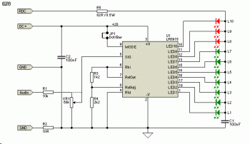
10 LEDs Audio VU Meter circuit with LM3915


This is very nice VU meter circuit for your own audio system project.

10 LEDs Audio VU Meter circuit

Build based IC LM3915, this circuit will indicate the power audio level of your audio system. This circuit is very simple, inexpensive and easy to build.

Visit this page for complete explanation. Follow the instruction and use the proper power supply for this circuit.

Wednesday 10 August 2011

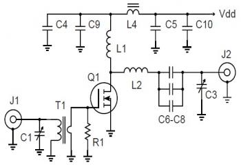
500W 27Mhz RF Amplifier Circuit


500W 27Mhz RF Amplifier Circuit diagram

Parts List:

C1,C3 = 75-380 pF mica trimmer, ARCO 465
C4-C8 = .01 uF 1 kV disc ceramic
C9,C10 = .1 uF 500V disc ceramic
L1 = 6 uH. 25t #24 ga.enam. 0.5" dia.
L2 = 210 nH. 4t #8 ga. .75" id, 1" long
L4 = 2t #20 PTFE on .5" ferrite bead m=850
Q1 = APT ARF448A
R1 = 25W 5W non-inductive
T1 = Pri: 4t #20 PTFE, Sec: 1t brass tube on 2 hole balun bead. Fair-Rite #2843010302 m=850


High voltage MOSFETs are now available that combine the best practices from the RF world with the economy of the switchmode devices and packaging. They are available in mirror image pairs and the heat spreader of the plastic TO-247 package is connected to the source.

Download the aplication note for this circuit 500W 27Mhz RF Amplifier HERE

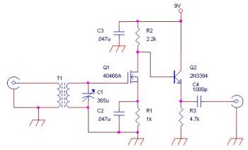
AM RF Amplifier Circuit for External Antenna


AM RF Amplifier Circuit for External Antenna

This is an AM RF Amplifier Circuit for External Antenna which built using RCA 40468A FET. The detailed explanation and recomendation about this circuit, go tothis page.

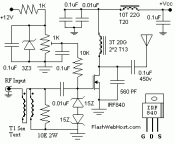
60W Linear RF Amplifier Circuit


electronic circuit diagram


The 60 Watt linear rf amplifier is easy all solid state circuit applying power mosfet IRF840. The IRF series of power transistors are provided in a number of voltage and power ratings. A single IRF840 can carry out maximum power output of 125 watts. Because these transistors are applied in inverters and smps, they're simply presented for about Rs: 20/-.

The IRF linear amplifier could be connected to the out put of well-known VWN-QRP to obtain an output of 60 Watts. The circuit draws 700 ma at 60 Volt Vcc. Great heat sink is actually a ought to for the power transistor.

Alignment of the circuit is quite effortless. Connect a dummy load to the out put of the circuit. It is possible to use some modest bulb like 24V 6Watts as the dummy load. I've even utilized 230V 60Watts bulb as dummy load with my IRF840 power amplifier working at 120Volts. Adjust the 10K preset to obtain about 100 ma Drain current. I applied gate voltage of 0.8V with my linear amplifier. A heigh gate voltage can make the power transistor get distroyed by self oscillation. So gate voltage ought to be below 2V and fixing at 1V is going to be secure.

Bifalar transformaer T1 is wound with 8 turns 26SWG on 1.4 x 1 balun core. The coil on the drain of IRF is 3 turns 20 SWG wound on 4 number of T13.9 torroids (two torroids are stacked to form a balun core). The RFC at the Vcc line is 20 Turns 20 SWG wound on T20 torroid.

60W Linear RF Amplifier circuit source:
http://www.flashwebhost.com/circuit/60_watts_rf_amplifier.php


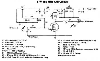
5W / 150MHz RF Amplifier Circuit

5W / 150Mhz RF Amplifier Circuit diagram


This is a 5W -150MHz RF amplifier circuit. It applies the MRF123 TMOSFET. The MRF123 is a very high gain FET which potentially unstable at both VHF and UHF frequencies, so the 68 Ohm input loading resistor has been used to enhance the stability. This RF amplifier has a gain of 14 dB and a drain effeciency of 55%.

Sunday 7 August 2011

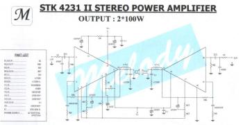
STK4231II, Stereo Amplifier 2x100 Watts

Do you want to make a simple amplifier, but has ability to deliver very high audio power output? If true, then the circuit is the answer for you. This circuit built using an IC for each channel, so you need two power ICs of STK4231II to make a stereo amplifier circuit.


STK4231II, Stereo Amplifier 2x100 Watts circuit

Each IC will deliver audio power output about 100W, so we can call this circuit as a 2x90W stereo power amplifier. This circuit must be supplied by using a dual polarity power supply and you have to install the heatsink on each IC to avoid overheating.

Download STK4231II datasheet:
Download Link

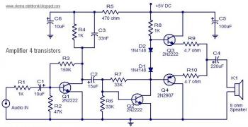
Audio Amplifier 4 transistors schematic


electronic circuit diagram


A very simple and easy to construct class AB audio amplifier by using 4 transistors is provided right here. In class AB operation every output device performs more than half of the input signal cycle. As much as 78% efficiency is possible with class AB types and cross over distortion is minimized. The circuit shown right here is suitable for small radio receivers, audio players, intercom, phone and so on.


Transistor Q1 with its connected components is wired as a pre-amplifier place. The audio input is coupled towards the base of Q1 through resistor R1 and capacitor C1. Resistor R3 provides collector to base bias for Q1 and C3 is an AC by pass capacitor for the collector resistor R4. Collector to base biasing is really a good method of biasing for circuits like this because it provides enough negative feedback, prevents thermal runway and stabilizes the operating point. The second stage will be the driver stage for the push pull pair. Q2 with its connected parts perform this job. This stage is also collector to base biased, and its input is coupled to the output from the pre-amplifier stage using capacitor C2. Resistor R8 limits the collector present of Q2.The third stage will be the class AB push pull section comprising of transistors Q3 and Q4. Diodes D1 and D2 offers the bias voltage for the push pull stage. The output from the amplifier is coupled towards the loud speaker via the capacitor C4. C5 and C6 are voltage source / power supply filter capacitors.

Circuit Notes:
  • K1 can be an 8 ohm/5Wof loud speaker.
  • The circuit may be assembled on a vero board.
  • C6 should be grounded close to towards the Q1 and C5 must be grounded close to towards the loud speaker ground. This reduces noise.
  • Use 5V DC for powering the circuit.

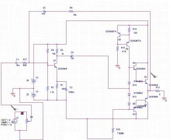
Transistored 15W Amplifier circuit schematic

The following diagram is a 15W power amplifier circuit which use power transistors as the main components. Make sure you are using coolrib/heatsink... :)


electronic circuit diagram

This amplifier uses a dual 20 Volt power supply and delivers 15 watts RMS into an 8 ohm load. Q1 operates in common emitter, the input signal being passed to the bias chain consisting of Q8, Q9, D6, D13 and D14. Q8 and Q9 provide a constant current through the bias chain to minimize distortion, the output stage formed by a discrete darlington pair (Q2,Q4) and (Q7,Q11). The last two transistors are power Transitors, specifically the 2N3055 and MJ2955. The 7.02K resistor, R16 was made using a series combination of a 4.7K, 680 Ohms, and two 820 Ohms. The 1.1K resistor, R3 was made using a 100 Ohms and a 1K resistor. You can use this circuit with any, MP3 player, walkman or CD player since it is designed to take a standard 500mv RMS signal.

Circuit design by Sergio Garcia de Alba Garcin
Source: http://www.zen22142.zen.co.uk/Circuits/Audio/amp15.htm

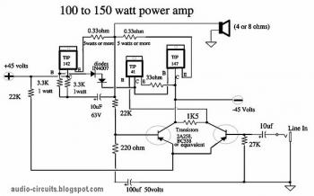
100W Power Amplifier


electronic circuit diagram


It is cheap and easy to make power amplifier which will deliver 100W - 150W power audio output. Great project choice for your Do-It Yourself amplifier project.

Circuit Notes:
  • This amplifier circuit requires dual polarity power supply. You may use this dual polarity power supply circuit
  • Use heatsink aluminium on the power transistor to prevent over heating.
  • The 45V power supply is the maximum, use 32V center tapped transformer.

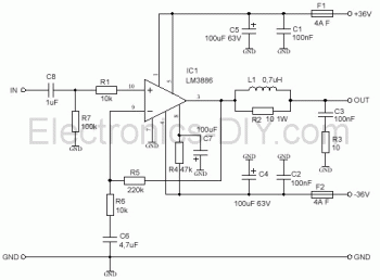
68W Power Amplifier Circuit based LM3886

The following diagram is a 68W Power Amplifier Circuit diagram based on famous amplifier chip LM3886.


electronic circuit diagram

Components List:
R1 = 10K Ohms
R2 = 10 Ohms 2W see text
R3 = 10 Ohms
R4 = 47K Ohms
R5 = 220K Ohms
R6 = 10K Ohms
R7 = 100K Ohms
L1 0,7uH
IC1 LM3886


C1 = 100NF
C2 = 100NF
C3 = 100NF
C4 = 100UF
C5 = 100UF
C6 = 4,7UF
C7 = 100UF
C8 = 1UF


Amplifier should be fed by source symmetrical good filtered of + 34 and – 34 volts. R2 and L1 is a resistor of 10 ohms / 2watt coiled with 10 to 12 you exhale of enameled thread AWG 20. The circuit integrated lm3886 is a component easy of being found at the electronics stores, for that he is used in several projects of potency audio, some exist circuits with linked lm3886 in bridges for potencies of up to 150 watts. For most information on the assembly of that circuit, please read the datasheet of the LM3886. With the information of the leaf of data you can adapt the circuit with LM3886 your needs

Circuit Source: http://electronics-diy.com/68-watts-lm3886-power-amplifier.php

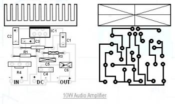
10W Audio Amplifier Circuit schematic

This is 10W mini audio amplifier circuit based TDA2003. The voltage supply is 9V, you may increase the voltage for higher gain (24V VCC max).


10W Audio Amplifier Circuit diagram

Parts List:
R1 : 2.2 Ohm
R2 : 220 Ohm
R3 : N/A
R4 : 10 KOhm pontesiometer
C1 : 2200 uF / 25V
C2 : 470 uF / 16V
C3 : 470 nF / 63V
C4 : 100 nF
C5 : N/A
C6 : N/A
IC1 : TDA 2003

18W Audio Amplifier Circuit based TIP41A/TIP42A schematic

This is an amplifier circuit capable to deliver 18 Watt RMS into 8 Ohm speaker. You do not need to build a preamplifier because the pre-amp already included in the this circuit based IC TLE2141C which is a low noise, high voltage, high slew-rate Op-amp.

18W Audio Amplifier Circuit based TIP41A/TIP42A

Amplifier parts list:
P1 = 22K Log. Potentiometer (Dual-gang for stereo)
R1 = 1K
R2 = 4K7
R3 = 100R
R4 = 4K7
R5 = 82K
R6 = 10R 1/2 watt
R7 = R22 4W Resistor (wirewound)
R8 = 1K 1/2W Trimmer Cermet (optional)
C1 = 470nF
C2,C5 = 100µF/3V Tantalum
C3,C4 = 470µF/25V
C6 = 100nF
D1 = 1N4148
IC1 = TLE2141C
Q1 = BC182
Q2 = BC212
Q3 = TIP42A
Q4 = TIP41A

Power supply parts list
R9 = 2K2 1/4W Resistor
C7,C8 = 4700µF 25V Electrolytic Capacitors
D2 = 100V 4A Diode bridge
D3 = 5mm. Red LED
T1 = 220V Primary, 15 + 15V Secondary, 50VA Mains transformer

18W Audio Amplifier Circuit Notes:

  • Can be directly connected to CD players, tuners and tape recorders.
  • Do not exceed 23 + 23V supply.
  • Q3 and Q4 must be mounted on heatsink.
  • D1 must be in thermal contact with Q1.
  • Quiescent current (best measured with an multimeter in series with Q3 Emitter) is not critical.
  • Adjust R3 to read a current between 20 to 30 mA with no input signal.
  • To facilitate quiescent current setting add R8 (optional).
  • A correct grounding is very important to eliminate hum and ground loops. Connect to the same point the ground sides of J1, P1, C2, C3 & C4. Connect C6 to the output ground.
  • Then connect separately the input and output grounds to the power supply ground

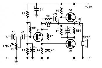
3W- 5W Audio Amplifier Circuit schematic

The following diagram is the class-a audio amplifier circuit. The circuit capable to deliver about 3W up to 5W power audio output.

Schematic diagram

3W- 5W Audio Amplifier Circuit diagram
Parts List:
R1 = 100K - 1/4W
R2 = 12K - 1/4W
R3 = 47K - 1/4W
R4 = 8K2 - 1/4W
R5 = 1K5 - 1/4W
R6 = 2K7 - 1/4W
R7,R9 = 100R - 1/4W
R8 = 560R - 1/2W
R10 = 1R - 1/2W
P1 = 47K Log. Potentiometer
C1,C2 = 10µF/63V
C3 = 47µF/25V
C4 = 100µF/35V
C5 = 150nF
C6,C7 = 220µF/25V
C8 = 1000µF/25V
Q1 = BC560C
Q2,Q3 = BD439

Circuit Notes:
  • Total electric current drawing of the circuit, recommended measured by inserting the probes of an multimeter across the positive output with the power supply and also the positive rail input with the amplifier, should be 700mA. Adjust R8 to obtain this value if needed.
  • Q2 and Q3 must be mounted on a finned heatsink of 120x50x25mm. minimum dimensions.
  • If needed, R2 could be modified to get 13V across C8 positive lead and negative ground.
  • Add R5 and C5 if the bass-boost facility is needed.


3W- 5W Audio Amplifier circuit source: redcircuits.com

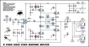
tSereo Headphone Amplifier "Studio Series"


Stereo Headphone Amplifier circuit diagram

Here the diagram of stereo headphone amplifier. The circuit called Studio Series Stereo Headphone Amplifier, of course this a top rated and high performance headphone amplifier circuit.

Stereo Headphone Amplifier Main Features:
  • High output power (up to 200mW; into 8Ω and 32Ω)
  • High performance – very low noise & distortion
  • Drives high and low-impedance headphones
  • Dual headphone sockets – can drive two pairs!
  • Works with a preamp or any line-level audio source
Measured Performance:
Frequency response = flat from 10Hz to 20kHz (see graphs)
Rated output power = 200mW into 8Ω and 32Ω, 85mW into 600Ω
Max. output power (current or voltage limited) = 575mW into 8Ω, 700mW into 32Ω, 130mW into 600Ω
Harmonic distortion = typically .0005% (600Ω load),.001% (32Ω load) and .005% (8Ω load)
Signal-to-noise ratio (A-weighted) = -130dB (600Ω), -120dB (32Ω) and -111dB (8Ω) with respect to 100mW output power.
Channel crosstalk = better than -68dB from 20Hz-20kHz at 100mΩ output power (see graphs)
Input impedance = ~47kΩ || 47pF
Output impedance = ~5Ω

Complete electronic project, go to this page

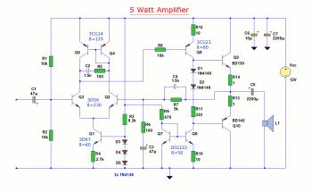
5W Audio Amplifier Circuit based BD139/BD140

The following is the diagram of 5W audio amplifier circuit which built using power transistor BD139 and BD140 as the final gaining process. This small amplifier can be used as general purpose amplifier such as computer amplifier, radio, mp3 player, video player, etc.

5W Audio Amplifier Circuit based BD139/BD140


Input Stage
The input stage consists of Q1 through Q5 and 3 diodes. The differential pair is biased by Q1, R3, R4, D3, D4, and D5. The biased current is set to 1 mA. Q4 and Q5 form a current mirror as the active load for the differential pair, and the output is taken out single-endedly from the collector of Q2. The open loop gain of the input stage is more than 60dB.

Second Stage
Q8 act as a common-emitter amplifier driving the output stage. Current mirror formed by Q6 and Q7 serve both biasing current source and active load for Q8. The open loop gain of the second stage is about 40dB. Q6 and Q7 are mounted together inside the blue tube to provide thermal compensation to each other.

Output Stage
The complimentary pair BD139/140 is biased by D1, D2, and R10. Adjusting the value of R10 can yield the desired quiescent current. R13 and R14 prevent thermal run-away of the complementary pair. DC voltage at the output is always half the power supply.

Feedback
The feedback network consists of R6, R5, C3 and C4. The overall gain is about the ratio of R6 to R5. C4 provides lead compensation; C3 provides DC-blocking.

Frequency Response
The cut-off frequency is determined at the upper end by C2, R5, and C4, and at the lower end by C1, C3, and C5.

Power
Power supply voltage 12V, 5W for a 4 ohm speaker, 3W for an 8 ohm speaker.

5W audio amplifier circuit page source: http://www.zen22142.zen.co.uk/Circuits/Audio/5w12v_amp.htm

Subwoofer Driver Circuit for Stereo Car Audio System

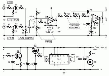
Here the schematic diagram of subwoofer driver for stereo car audio system. You may use this circuit for your home audio system.
Subwoofer Driver Circuit for Stereo Car Audio System
Components Part:

R1,R4 = 1K
R2,R3,R5,R6 = 10K
R7,R8 = 100K
R9,R10,R13 = 47K
R11,R12 = 15K
R14,R15,R17 = 47K
R16 = 6K8
R18 = 1K5
P1 = 10K Log Pot
P2 = 22K Dual gang Linear Pot
D1 = LED
Q1,Q2 = BC547

Circuit Notes:
  • The circuit connected to the output of existing amplifier. Take note that this circuit is not an amplifier, it just similar to crossover circuit.
  • Use heatsink to IC2 to keep the IC from overheating.

C1,C2,C3,C6 = 4µ7/25V
C4,C5 = 68nF
C7 = 33nF
C8,C9 = 220µF/25V
C10 = 470nF
C11 = 100nF
C12 = 2200µF/25V
IC1 = TL072
IC2 = TDA1516BQ
SW1 = DPDT Switch
SW2 = SPST Switch (current handling min 3A)
SPKR = 4 Ohm Woofer or paralled two 8 Ohm Woofers


100W Guitar Power Amplifier circuit

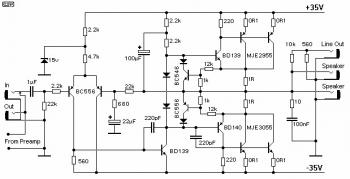
Here the guitar power amplifier circuit which will deliver about 100W audio output. This is transistored amplifier, heatsink is a must.


100W Guitar Power Amplifier circuit


The speaker and line out connections allow up to two 8 Ohm speaker cabinets (giving 4 Ohms), and a line level output for connection to a direct injection (DI) box. The level is about 1.3V (or +5dBm) at full undistorted output - change the 560 Ohm resistor to modify the level if desired.
The two 1 Ohm resistors must be rated at 10 Watts (they will still get quite hot, so mount them well away from other components). These can be mounted to the heatsink with small brackets if you want to keep them a bit cooler - remember to ensure that the heatsink can handle the extra heat input, as these two will add about 10 Watts of additional heat energy. The four 0.1 Ohm resistors should be 5W types. The amp is otherwise quite conventional. Use the parallel arrangement as shown, anything less will cause the transistors to be operated outside their safe operating area, which will result in the eventual failure of the output stage.

Make sure that the two bias diodes are mounted well clear of anything that gets hot - including the heatsink. These diodes are the two in series. All diodes should be 1N4001 (or 1N400? - anything in the 1N400x range is fine). A heatsink is not needed for any of the driver transistors.

The life of a guitar amplifier is a hard one, and I suggest that you use the largest heatsink you can afford, since it is very common to have elevated temperatures on stage (mainly due to all the lighting), and this reduces the safety margin that normally applies for domestic equipment. The heatsink should be rated at 0.5 degree C/Watt to allow for worst case long term operation at up to 40 degrees C (this is not uncommon on stage).

Make sure that the speaker connectors are isolated from the chassis, to keep the integrity of the earth isolation components in the power supply.

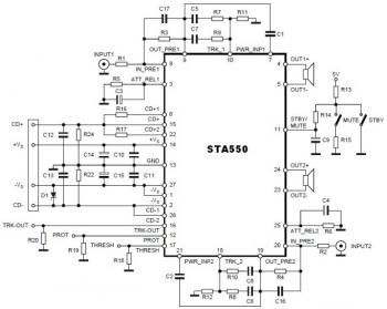
70W Stereo Audio Amplifier Circuit based STA550 amp


70W Stereo Audio Amplifier based STA550

This is a stereo amplifier circuit diagram. The amplifier will produce stereo output channel with the power audio output can reach up to 70W for each channel. The amplifier built based great amplifier chip STA550 from STMicroelectronics. Take a note that this amplifier is a bridge amplifier, the speaker's terminal should not connected to the ground line.

Download STA550 Datasheet for your amplifier project reference.

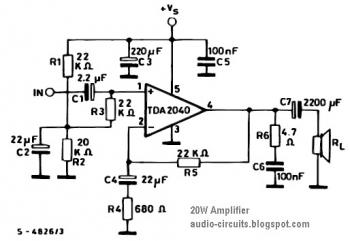
20W Power Amplifier Circuit based TDA2040 amp

The following diagram is the circuit diagram of power amplifier based power IC TDA2040. The circuit capable to deliver power audio output up to 20W with single power supply. The TDA2040 is intended for use as a class AB audio amplifier.


20W Power Amplifier Circuit based TDA2040
The TDA2040 delivers great output current and has quite low harmonic and cross-over distortion. Further the device incorporates a patented short circuit protection program comprising an arrangement for automatically limiting the dissipated power so as to keep the working point on the output transistors within their secure operating area. A thermal shut-down method is also included.

You can download the TDA2040 datasheet here

20W Power Amplifier Circuit based TDA2040

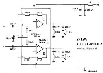
TDA1521 - 12W Stereo Amplifier Circuit


TDA1521 - 12W Stereo Amplifier Circuit diagram

This is the circuit diagram of 12W stereo audio power amplifier. The amplifier powered by a single power chip TDA1521. The TDA1521 contains two amplifier module. The TDA1521 has two input channel and two output channel, so, you'll only need a TDA1521 for a stereo amplifier circuit.

Source: 12W stereo amplifier

Friday 5 August 2011

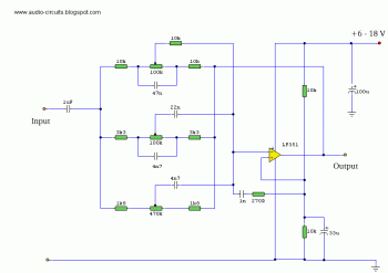
Equalizer 3 band

This is mono 3 band equalizer circuit. The circuit is simple, cheap and easy to built. You should make two circuits for your stereo audio system.

electronic circuit diagram


Supply voltage may be anything from 6 to 30 Volts. Maximum boost 20dB is only realized with maximum supply voltage.